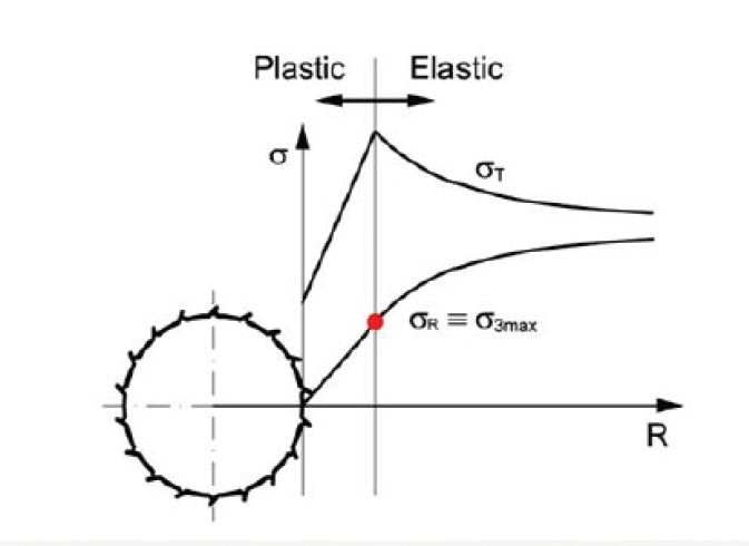
Introduction
"Multiple graph" approach designed for the preliminary assessment of rock mass behavior during tunnel excavation. By utilizing a four-sector logical framework, the method quantifies rock mass fabric, strength, competency, and self-supporting capacity to identify potential geological hazards. Key metrics such as the Geological Strength Index (GSI) and Rock Mass Rating (RMR) are integrated to predict phenomena like squeezing, spalling, and rockbursts. This tool serves both the initial design phase for hazard detection and the construction phase for selecting appropriate support measures at the tunnel face. Through empirical correlations and probabilistic analysis, the approach provides a systematic way to simplify complex geomechanical data into actionable engineering insights. The author concludes that while based on simplified assumptions, the graphs offer a robust and user-friendly tool for managing risks in underground rock engineering.
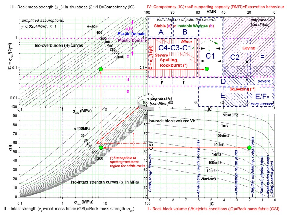
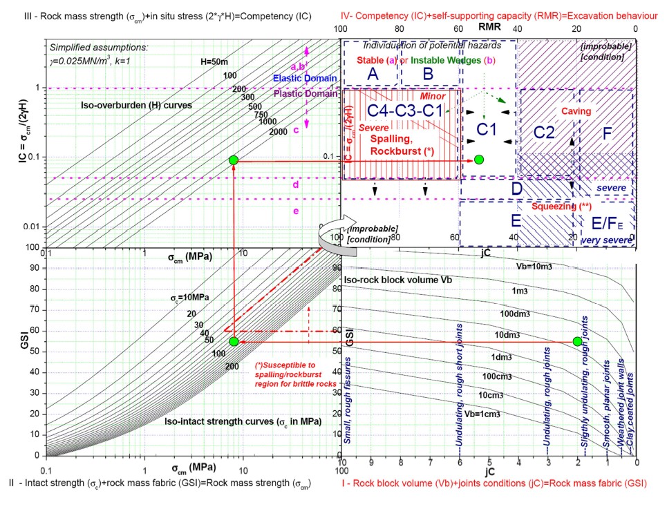 **Figure 1 - Multi Graph **
How do the four quadrants predict tunnel excavation hazards?
The multiple graph predicts tunnel excavation hazards through a four-step logical sequence that quantifies geomechanical properties, starting from the lower right quadrant and progressing clockwise. Each quadrant builds upon the results of the previous one to ultimately identify potential typical deformation phenomena (hazards).
1. Quadrant I: Estimation of Rock Mass Fabric (Lower Right)
The process begins by determining the Rock Mass Fabric, quantified as the Geological Strength Index (GSI).
- Inputs: Rock block volume (V_b) and joint condition factor (jC). To determine GSI value through rock coring visit we have tool on our website which help in determining GSI values through rock bore logs. Read our blog "How to determine GSI through core logging?" for more information.
- Outcome: This quadrant provides a quantitative estimation of the rock mass structure, which is essential for scaling down intact rock strength to the strength of the actual rock mass.
2. Quadrant II: Estimation of Rock Mass Strength (Lower Left)
The next step calculates the Rock mass strength (sigma_cm) using the fabric index derived in the first quadrant.
- Inputs: GSI (from Quadrant I) and Intact rock strength (sigma_c).
- Outcome: By intersecting these values, the graph identifies the rock mass strength based on the Hoek-Brown failure criterion. This quadrant also highlights regions specifically susceptible to spalling or rockburst for brittle rocks.
The value of rock mass strength can also be determined through our another tool called Rock Mass Properties present on our website. Read our blog on AI Powered Rock Mass Properties Calculator.
Considerations for Brittle Rock In cases of good quality, hard, and brittle rock masses, the sources note that a "spalling type" failure might occur instead of a shear failure . For these rocks (where the Brittle Index IF =σc/σt >8), the actual mobilized strength at failure may differ from the σcm calculated via GSI-based equations, depending on stress levels and crack initiation, . Quadrant II highlights a specific region susceptible to this hazard, typically where both GSI and σc are greater than 60
3. Quadrant III: Estimation of Rock Mass Competency (Upper Left)
This quadrant evaluates the Rock mass competency (IC), which is the ratio between the rock mass strength and the tangential stress on the excavation contour.
- Inputs: Rock mass strength (sigma_cm) and In situ stress (derived from overburden (H).
- Outcome: This step separates the excavation response into two main domains:
- Elastic Domain (IC > 1): Generally associated with stable conditions or wedge instabilities.
- Plastic Domain (IC < 1): Associated with more complex deformation phenomena like squeezing.
4. Quadrant IV: Identification of Potential Hazards (Upper Right)
The final quadrant integrates the competency index with the rock mass's self-supporting capacity to identify specific excavation hazards.
- Inputs: Competency Index (IC) and RMR (Rock Mass Rating).
- Outcome: The graph delimits specific hazard zones based on the geostructural quality and stress conditions:
- Stable or Unstable Wedges: Occurs in good rock masses under low stress conditions.
- Spalling/Rockburst: Brittle, stress-driven instabilities in hard rock.
- Squeezing: Pronounced time-dependent deformations in low-strength, high-deformability rocks.
- Caving: Generic gravitational collapse of highly fractured rock masses with poor self-supporting capacity.
Based on these predictions, designers can focus on detected potential problems and select the most adequate support section types for the tunnel face.
Hazard Diagnostic Matrix
The hazard diagnostic Matrix (referred to in the sources as the GDE classification scheme of the excavation behaviour) is a tool used to identify and categorize potential tunnel excavation hazards by integrating tensional analysis with geostructural quality.
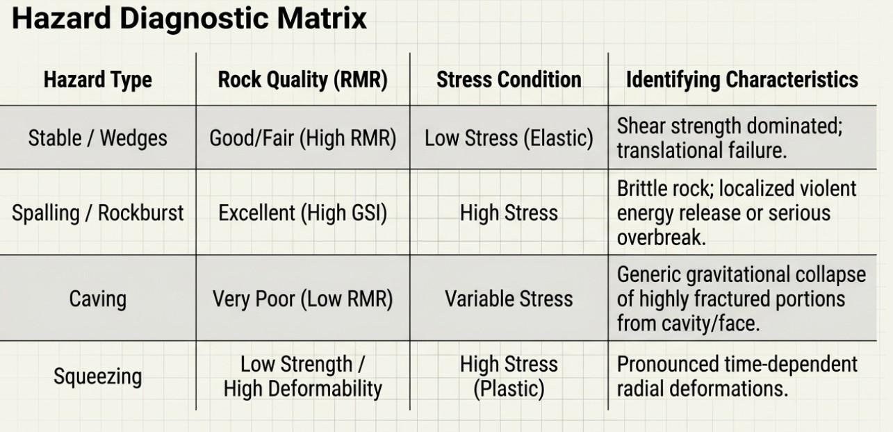 Figure 2 - Hazard Diagnostic Matrix
This matrix allows designers and engineers to focus on detected potential problems and implement the most adequate methods of analysis and support.
Core Components of the Matrix
The matrix operates by cross-referencing two primary geomechanical indices derived from the earlier quadrants of the multiple-graph approach:
- Tensional/Deformational Response: This axis uses the Behavioural Category (a through f), which is defined by the radial deformation at the face (delta o), the extension of the plastic zone (Rp/Ro), and the Competency Index (IC).
- Geostructural Quality: This axis uses the Rock Mass Rating (RMR) to categorize the rock mass into classes (I through V), reflecting its self-supporting capacity.
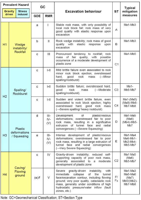
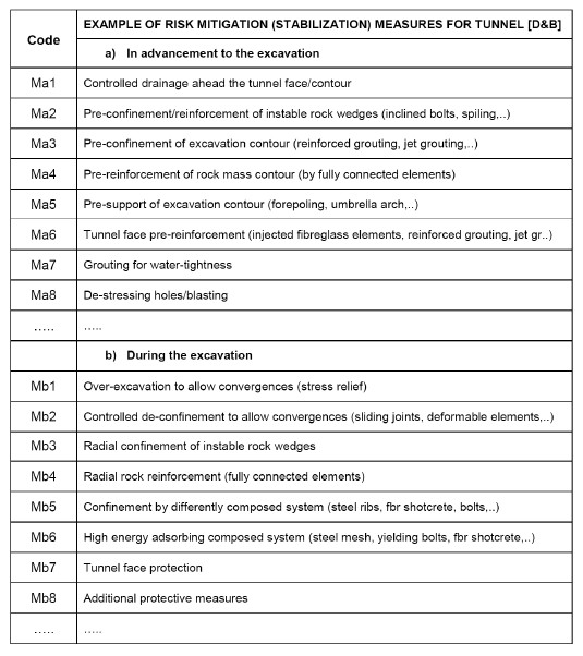
Figure 3 - Excavation Behaviour & Typical Mitigation Measures
Hazards Identified in the Matrix as shown in Figure 3
The matrix delimits five main types of excavation behavior and hazards:
- Stable: Associated with very good quality rock masses (RMR I) and elastic response (Category a).
- Unstable Wedges: Occurs in good quality rock masses (RMR II) where the excavation response is dominated by the shear strength of discontinuities.
- Spalling / Rockburst: Stress-driven instabilities characterized by brittle failure in hard, good quality rock masses (Category c, RMR I-II) under overstress conditions.
- Squeezing: Pronounced time-dependent plastic/viscous deformations occurring in low-strength, high-deformability rocks under overstress (Category d-e, RMR III-V).
- Caving: Generic gravitational collapse of portions of highly fractured rock mass with poor self-supporting capacity (RMR IV-V), often leading to immediate collapse of the tunnel face.
Practical Application
The matrix serves as a bridge between hazard identification and engineering solutions:
- Risk Mitigation: It associates specific typical mitigation measures (such as controlled drainage, pre-reinforcement, or yielding bolts) to different hazard types and intensities.
- Support Selection: It defines the field of application for pre-defined support section types (e.g., Section Types A, B, C1, D, E, F) based on the expected geomechanical hazard.
- Design Orientation: In preliminary phases, it helps orient detailed numerical calculations toward the most critical scenarios identified by the matrix.
Conclusion
The article concludes that the updated GDE "multiple graph" approach is a robust and efficient tool for the preliminary assessment of rock mass excavation behavior and the identification of potential tunnelling hazards.
The primary conclusions of the article are as follows:
- Logical Quantification Sequence: The method successfully predicts excavation response by quantifying four key geomechanical properties in a specific logical order: (1) fabric, (2) strength, (3) competency, and (4) self-supporting capacity.
- Dual-Phase Utility: Despite relying on simplified assumptions (such as a circular tunnel in an equivalent-continuum rock mass), the author concludes that the method is valuable in two distinct stages:
- Preliminary Design: It allows for the rapid identification of critical scenarios and helps engineers perform sensitivity analyses to orient future detailed studies.
- Construction Phase: It provides a rational basis for selecting the most appropriate support section types at the tunnel face based on real-time geomechanical observations.
- Design Optimization: The author emphasizes that this preliminary analysis enables the design team to focus their attention and resources on specifically detected potential problems. By identifying these hazards early, more complex numerical analyses and calculations can be implemented only where they are truly required, improving the overall detail and safety of the tunnel design.
Ultimately, the article presents the "multiple graph" as a "user-friendly" bridge between geomechanical classification and practical engineering solutions for mitigation and support.
We are trying to develop this tool through which you can able to predict the Excavation Type and it Support System.
References
The references for this article, as listed in the Bibliography section of the source material, are as follows:
- "An Update of the 'Multiple Graph' Approach for the Preliminary Assessment of the Excavation Behaviour in Rock Tunnelling" and was written by G. Russo from Geodata Engineering (GDE)
- Anagnostou, G., Kovari, K., 2003. The stability of tunnels in grouted fault zones, Mitteilungen des Inst. für Geotechnik der ETH, Zürich.
- Antolovic, M., Filipovic, A., Amadini, F., 2013. Engineering geological behaviour of rock mass in Chenani Nashri tunnel: the largest road tunnel in India, ITA symposium Croatia.
- Bandis, S.C., 1997. Rock characterization for Tunnelling – A Rock Engineer’s Perspective, Feldsbau 15, Nr.3.
- Bieniawski, Z.T., 1984. Rock Mechanics Design in Mining and Tunneling, Balkema, Rotterdam.
- Bieniawski, Z.T., 1989. Engineering Rock Mass Classification, John Wiley & Son.
- ** Cai, M., Kaiser, P.K., H., Tasaka, Y., Minami, M., 2007.** Determination of residual strength parameters of jointed rock masses using the GSI system, International Journal of Rock Mechanics & Mining Sciences.
- Carranza-Torres, C., 2004. Elasto-plastic solution of tunnel problems using the generalized form of the Hoek–Brown failure criterion, Proceedings of the ISRM SINOROCK.
- Decman, A., Stella, F., Verzani, L.P., 2013. Geomechanical follow-up of El Teniente new mine level access tunnels, ITA symposium Croatia.
- Diederichs, M.S., Kaiser, P.K., Eberhards, E., 2004. Damage initiation and propagation in hard rock during tunnelling and the influence of near-face stress rotation, Int. Journal of Rock Mechanics and Mining Science.
- Diederichs, M.S., 2005. General Report: Summary of Meetings with Geodata with recommendations towards a Design Methodology for spalling Failure and Rockburst Hazards, Personal communication.
- Diederichs, M.S., Carter, T., Martin, D., 2010. Practical Rock Spall Prediction in Tunnels, ITA World Tunnel Congress Vancouver.
- Filipovic, A., Antolovic, M., Angelakis, C., 2013. Design follow-up of Chenani Nashri tunnel construction, ITA symposium Croatia.
- Hoek, E., Brown, E.T., 1980. Underground Excavations in Rock, The Institution of Mining and Metallurgy, London.
- Hoek, E., Diederichs, M., 2006. Estimation of rock mass modulus, Int. Journal of Rock Mechanics and Mining Science.
- Hoek, E., Carranza-Torres, C., Diederichs, M.S., Corkum, B., 2008. Integration of geotechnical and structural design in tunnelling, Proc. Univ. of Minnesota 56th Annual Geotechnical Engineering Conference.
- Hoek, E., Marinos, P., 2000. Predicting Squeeze, Tunnels and Tunnelling International.
- Hoek, E., Carranza-Torres C., Corkum, B., 2002. Hoek-Brown failure criterion, 2002 Edition, Proc. North American Rock Mechanics Society.
- Hoek, E., Kaiser, P.K., Bawden, W.F., 1995. Support of Underground Excavations in Hard Rock, Balkema, Rotterdam.
- Kaiser, P.K., 1994. Rockmass failure and implications for support design, 5° Ciclo di Conferenze di Meccanica e Ingegneria delle Rocce, Politecnico di Torino.
- Kontrec, P., Constandinidis, V., 2013. Engineering geological characterization of the rock mass in the Adit P4600, Project El Teniente, Chile, ITA symposium Croatia.
- Kovari, K., 1998. Tunnelling in Squeezing Rock, Tunnel Nr.5.
- Marinos, P., Hoek, E., 2001. Estimating the geotechnical properties of heterogeneous rock masses such as Flysch, Bull. Engg. Geol. Env..
- Martin, C.D., Kaiser, P.K., McCreath, D.R., 1999. Hoek–Brown parameters for predicting the depth of brittle failure around tunnels, Can. Geotech. Journal.
- Palmstrom, A., 1996. Characterizing rock masses by the RMi for use in practical rock engineering, Tunn. and Und. Space Tech..
- Palmstrom, A., 2000. Recent developments in rock support estimates by the RMi, Journal of Rock mechanics and tunneling technology.
- Palomba, M., Russo, G., Amadini, F., Carrieri, G. Jain, A.R., 2013. Chenani-Nashri Tunnel, the longest road tunnel in India: a challenging case for design-optimization during construction, World Tunnel Congress, Geneva.
- Russo, G., Kalamaras, G.S., Grasso P., 1998. A discussion on the concepts of geomechanical classes, behavior categories and technical classes for an underground project, Gallerie e grandi opere sotterranee.
- Russo, G., Grasso, P., 2006. Un aggiornamento sul tema della classificazione geomeccanica e della previsione del comportamento allo scavo, Gallerie e grandi opere sotterranee.
- Russo, G., Grasso, P., 2007. On the classification of the rock mass excavation behaviour in tunnelling, Proc. 11th Congress of ISRM, Lisbon.
- Russo, G., 2007. Improving the reliability of GSI estimation: the integrated GSI-RMi system, Proc. I.S.R.M. Workshop.
- Russo, G., 2008. A simplified rational approach for the preliminary assessment of the excavation behaviour in rock tunnelling, Tunnels et Ouvrages Souterraines.
- Russo, G., 2009. A new rational method for calculating the GSI, Tunnelling and Underground Space Technology.
- Tzamos, S., Sofianos, A.I., 2007. A correlation of four rock mass classification systems through their fabric indices, Intern. Journal of Rock Mechanics and Mining.