
1. Understanding 2D Tunnel Analysis
Foundation and Purpose
Tunnelling is inherently 3D, but 2D numerical analysis remains the primary tool for preliminary tunnel design and support performance assessment.
1.1 What is 2D Analysis?
- Simulates 3D excavation in a 2D plane by modelling a cross-sectional "slice"
- Uses plane strain or axisymmetric formulations
- Applies internal pressure relaxation or boundary displacement
1.2 Why Use 2D Analysis?
- Cost-effective for preliminary design
- Computationally efficient, fast results
- Widely understood and accepted
- Suitable for simple geometries and stress conditions
- Provides rapid squeezing potential assessment
2. The 2D Analysis Approach - Methodology and Key Concepts
Longitudinal Displacement Profile (LDP): Describes how tunnel wall displacement develops during excavation. Critical for accurate 3D simulation.
2.1 Common 2D Methods
- Convergence-Confinement (stress relief)
- Field stress vector reduction
- Face replacement/destressing
- Concentric ring excavation
All methods replicate progressive 3D stress redistribution.

3. When 2D Analysis Works Best - Ideal Conditions for Accurate Results
3.1 Geometric Conditions
- Circular/simple shapes (low aspect ratio)
- Regular, symmetric cross-sections (horseshoe tunnels acceptable)
- Full-face excavation or widely-spaced sequential stages
3.2 Stress & Material Conditions
- Isotropic stress fields (K ≈ 1.0)
- Homogeneous rock mass
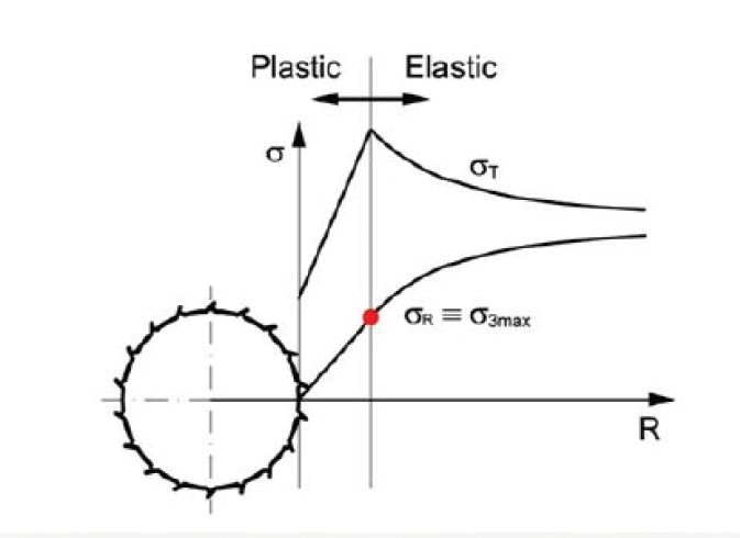
- Moderate plastic zone development (Rp/Rt < 5-6)
Under these conditions, 2D plane strain analysis with proper LDP calibration can predict tunnel behavior for preliminary design.
4. Critical Limitations of 2D Analysis - When Results Become Unreliable
4.1 Anisotropic Stresses - HIGH IMPACT
- Stresses differ significantly (K ≠ 1)
- Cause uneven deformation and incorrect load predictions
- Miss stress redistribution
4.2 Complex Geometries - MODERATE IMPACT
- Non-circular/complex shapes reduce accuracy
- Corner stress concentrations and asymmetric displacement
4.3 Staged Excavation - HIGH IMPACT
- Close excavation of heading & bench stages
- 2D fails to model stage coupling, leading to inaccurate deformation
4.4 Support Near Face - MODERATE IMPACT
- Stiff support installed near face invalidates LDP
- Requires modified LDP accounting for support timing
5. The Anisotropic Stress Problem
5.1 Core Issue
Standard 2D models assume isotropic stress (K=1.0). When K ≠ 1.0:
- Displacement profiles become directionally inconsistent
- Violates uniform radial displacement assumption

5.2 Research Findings
- At K = 1.5: Horizontal/vertical LDPs differ by >30%
- Standard LDP functions become invalid for anisotropic stress
- Recommendation: 3D analysis required for K significantly different from 1.0
6. Staged Excavation Challenge
6.1 Assumption vs. Reality
- Common Assumption: Reuse analysis sequence for all excavation stages
- Reality: Valid only when stages are >12-20 tunnel radii apart
- Problem: Close sequencing creates 3D interactions 2D models cannot capture
6.2 What Happens
- Face softening as bench approaches
- Coupled deformation from both stages
- Modified LDP during multi-stage excavation
- Load redistribution affecting support performance
6.3 Design Implications
- 2D analysis requires >12-20R spacing between stages
- Closely spaced excavations need 3D analysis
- Support timing becomes critical in staged designs
- Minimum 60-100m separation for 10m diameter tunnels
7. Practical Implementation Guidelines
Best Practices for Reliable 2D Analysis
7.1 Model Setup
- Boundary conditions: >12-16 tunnel radii from excavation
- Mesh quality: Finer near tunnel boundary
- Element type: 6-node triangular elements
- Model size: 2-3x plastic zone extent
7.2 Analysis Method
- Stress vector method (K≠1); face replacement (K≈1)
- Minimum 15-20 excavation steps for smooth GRC
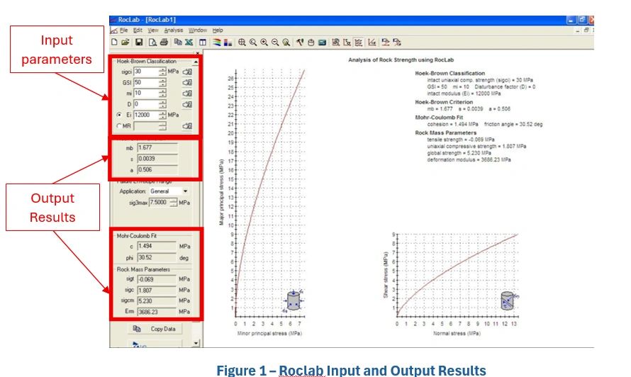
- Use validated LDP functions (e.g., Vlachopoulos & Diederichs 2009)
- Ensure convergence at each stage
7.3 Validation & QC
- Cross-check pressure reduction vs. face replacement methods
- Sensitivity analysis for boundary distance, mesh density
- 3D validation for critical sections
- Document assumptions (K-value, geometry simplifications)
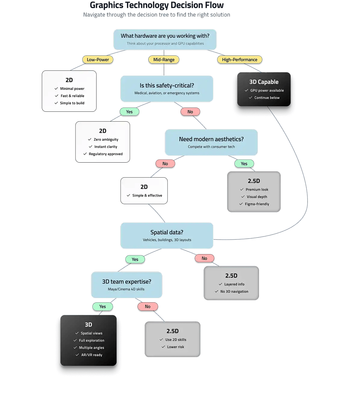
8. Decision Framework
When to Use 2D vs. 3D Analysis
9. Key Takeaways

10. References
- Nicholas Vlachopoulos & Mark S. Diederichs, Geotechnical and Geological Engineering (2014)