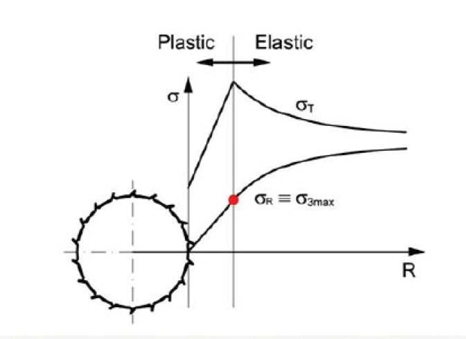
The attached image illustrates the stress distribution around a circular opening, such as a borehole or a tunnel, in a material that exhibits both elastic and plastic behaviour. This is a classic representation used in geomechanics and rock mechanics to describe the "Plastic Zone" that forms when the stress around an excavation exceeds the strength of the rock or soil.
Key Components of the Image
1. The Physical Model (Left)
The circular feature with jagged edges represents a cross-section of a borehole or tunnel. The dashed center line indicates the axis of symmetry. The jagged lines often represent the "breakout" or damaged zone where the material has failed.
2. The Axes
- R (Horizontal Axis): Represents the radial distance from the center of the opening.
- σ (Vertical Axis): Represents the magnitude of the stress.
3. Stress Curves
- σT (Tangential/Hoop Stress): This is the stress acting around the perimeter of the hole. In the elastic zone, it is highest near the opening and decreases as you move further away. However, because the material near the wall has failed (Plastic Zone), the peak stress is pushed further into the rock mass.
- σR (Radial Stress): This is the stress acting perpendicular to the wall of the hole. It starts at a low value (or zero if there is no internal support) at the wall and increases as you move deeper into the material. The red dot highlights σR≡σ3max, indicating the maximum radial stress at the boundary between the plastic and elastic zones.
Explanation of the Zones
Plastic Zone
This is the region immediately surrounding the opening where the induced stresses have exceeded the yield strength of the material. In this zone:
- The material has undergone permanent deformation or failure.
- The tangential stress (σT) increases as you move away from the wall because the failed material can only support a limited amount of load, transferring the excess "peak" stress deeper into the solid rock.
Elastic Zone
Beyond a certain radius, the stresses drop below the yield strength of the material. In this zone:
- The material behaves elastically, meaning it would theoretically return to its original shape if the load were removed.
- The tangential stress (σT) gradually decreases and the radial stress (σR) gradually increases until they both reach the level of the original "in-situ" or far-field stress of the ground.
Summary of the Phenomenon
This graph shows that the highest stress is not actually at the wall of the tunnel, but at the interface between the plastic and elastic zones. Engineers use this information to determine how much support (like rock bolts or concrete lining) is needed to stabilize the opening. If the plastic zone is too large, the tunnel may collapse without significant reinforcement.