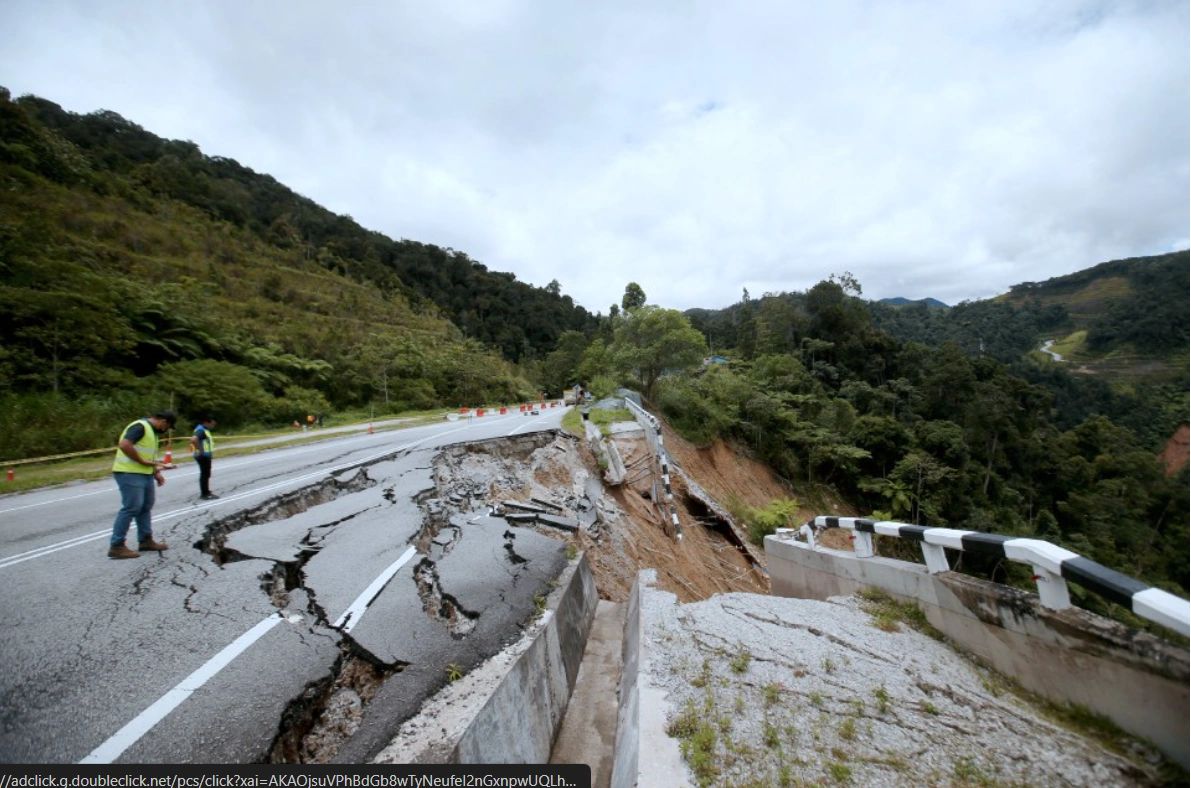
Slopes are everywhere in civil and infrastructure projects road batters, rail cuttings, residential excavations, embankments, quarry walls, and natural hillsides. When a slope moves, the consequences can be significant: safety risks, service interruptions, costly repairs, and reputational damage.
This blog explains the mechanics of slope stability in clear, practical terms what makes slopes stand up, what makes them fail, and how geotechnical engineers assess and manage slope risk in real projects.
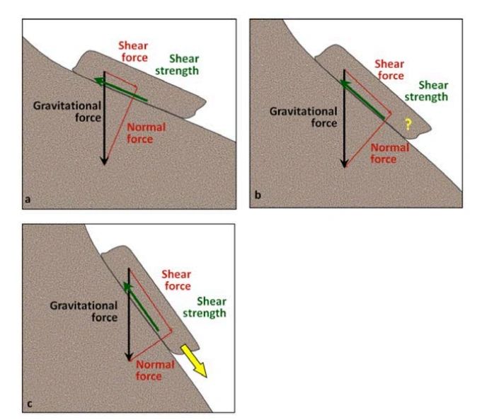
1) What "slope stability" really means
Slope stability is the balance between:
- Driving forces that tend to pull soil/rock downslope (primarily gravity and any additional loads), and
- Resisting forces provided by the ground's shear strength and any stabilising measures.
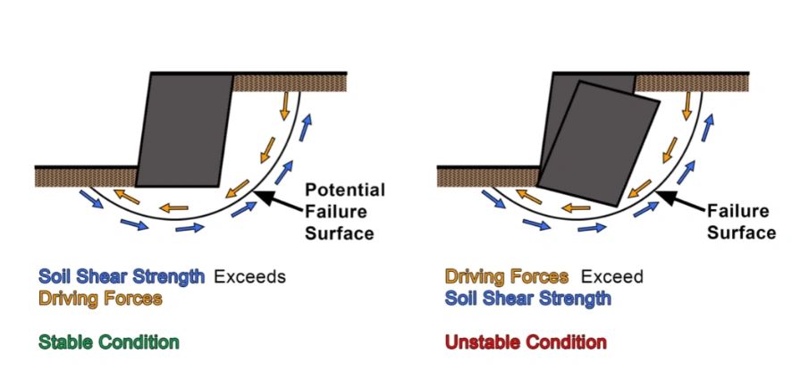
When driving forces exceed resisting forces along a potential failure surface, the slope can deform or fail.
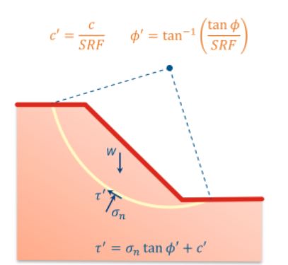
Engineers often express this balance as a Factor of Safety (FoS):
- FoS > 1.0 indicates stability for the assumed conditions
- FoS ≈ 1.0 indicates the slope is at/near failure
- Design targets are typically greater than 1.0 to account for uncertainties (ground variability, modelling assumptions, future water conditions, construction effects).
2) Shear strength: the core of the problem
The resisting side of slope stability is mostly the ground's shear strength. For many soils, a common way to describe shear strength is via effective stress (i.e., the stress carried by the soil skeleton, not the pore water).
A widely used representation is the Mohr–Coulomb model
Where:
- τf = shear strength at failure
- c′ = effective cohesion (can be real, apparent, or modelled)
- σ′ = effective normal stress on the potential slip surface
- ϕ′ = effective friction angle


Key takeaway: shear strength increases with effective normal stress but effective stress can drop dramatically if pore water pressures rise.
3) Why water is often the trigger
Many slope problems are not caused by changes in soil type or geometry, they're triggered by changes in groundwater and drainage.
Pore water pressure (u) reduces effective stress:

So when rainfall, seepage, blocked drains, leaking services, or seasonal groundwater rise increases u, the shear strength reduces and the slope may move.
Common water-related triggers include:
- prolonged rainfall and wet seasons
- poor surface drainage and ponding near the crest
- seepage forces in sandy/silty soils
- artesian or confined groundwater pressures
- rapid drawdown (e.g., reservoir/river level drops)
- construction exposing permeable layers or preferential flow paths
4) Typical slope failure mechanisms
Not all slope failures look the same. The failure mechanism depends on material type, layering, structure, groundwater, and geometry.
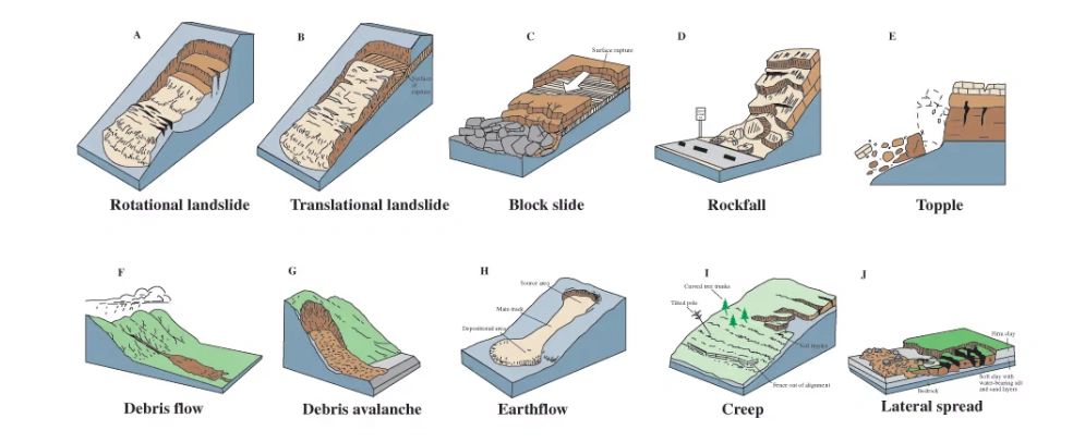
a) Rotational (circular) failure
Common in cohesive soils (clays and clayey fills). The slip surface is often curved, and movement can be progressive.
b) Translational (planar) failure
Common in layered soils or weak interfaces (e.g., clay seam beneath sand, fill over soft natural ground). The mass slides along a relatively planar surface.
c) Wedge failure (rock slopes)
In rock cuttings, failure may occur along intersecting discontinuities (joint sets, bedding planes, faults) forming a wedge that can slide or topple.
d) Toppling
In steep rock faces or heavily jointed materials, blocks can rotate forward about a pivot—often influenced by discontinuity orientation and erosion at the toe.
e) Shallow instability / raveling
Often in granular soils or weathered materials; can involve small slips, erosion, or face unraveling especially if unsupported or poorly compacted.
5) The role of geometry and loading
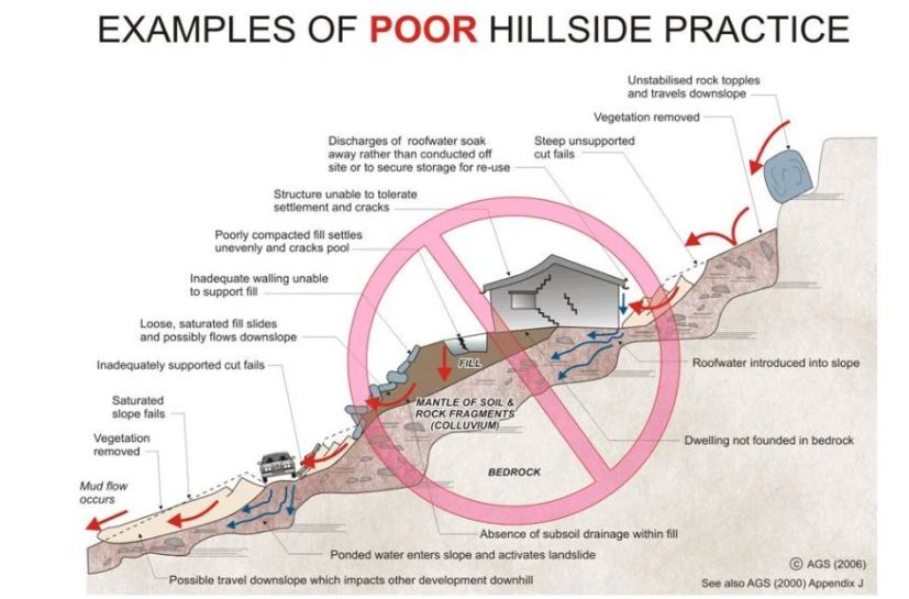
Even with unchanged material properties, slopes become less stable when we:
- steepen the slope angle
- increase slope height
- add loads near the crest (buildings, stockpiles, traffic, retaining surcharge)
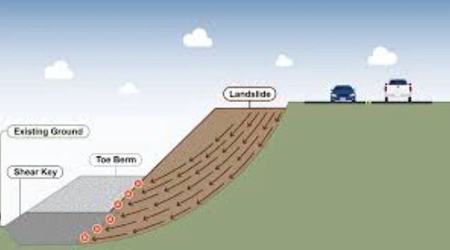
- remove toe support (excavation at the base, erosion, creek scour)
Small changes can matter. For example, placing a spoil pile near the crest often increases driving forces and can also worsen infiltration two destabilising effects at once.
6) How engineers analyse slope stability
Engineers typically assess slopes using a combination of:
a) Site observations and ground model development
A stability assessment is only as good as the ground model. This includes:
- stratigraphy (layering, weak seams)
- material strength and stiffness
- groundwater regime (perched water, seepage zones)
- evidence of past movement (scarps, tension cracks, leaning trees/fences, hummocky ground)
b) Laboratory and in-situ testing
Depending on the project, this may include:
- triaxial or direct shear testing
- Atterberg limits and classification
- SPT/CPT correlations for strength parameters
- permeability testing where seepage is critical

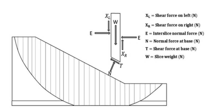
c) Limit equilibrium analysis (LEA)
This is the most common method used in design. The soil mass is divided into slices and equilibrium equations are solved to estimate FoS. Methods may include Bishop, Janbu, Spencer, Morgenstern Price.
LEA is widely used because it's robust, transparent, and fits typical design workflows.
d) Numerical modelling (when needed)
Finite element/finite difference methods can be useful where:
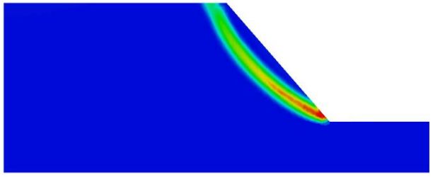
- deformations (not just FoS) matter
- staged construction affects stability
- complex groundwater/seepage needs coupling
- soil–structure interaction is important
- reinforcement systems require detailed modelling
7) Short-term vs long-term stability (and drained vs undrained)
A common source of confusion is which strength parameters to use.
- Short-term (undrained) conditions may control during or immediately after excavation in clays, where pore pressures haven't dissipated.
- Long-term (drained/effective stress) conditions often control for permanent slopes, especially where groundwater equilibrium and seasonal variation are relevant.
Good design checks the relevant cases, including credible worst-case groundwater conditions.
8) Stabilisation and risk-reduction options
Stabilisation isn't one-size-fits-all. The best solution depends on mechanism, constructability, access, budget, and long-term maintenance.
Common measures include:
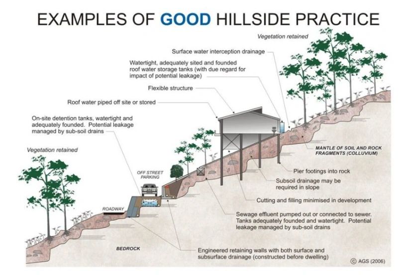
a) Geometry changes
- flattening the slope
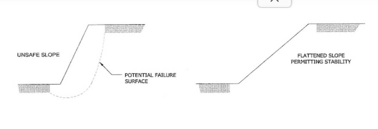
- creating benches
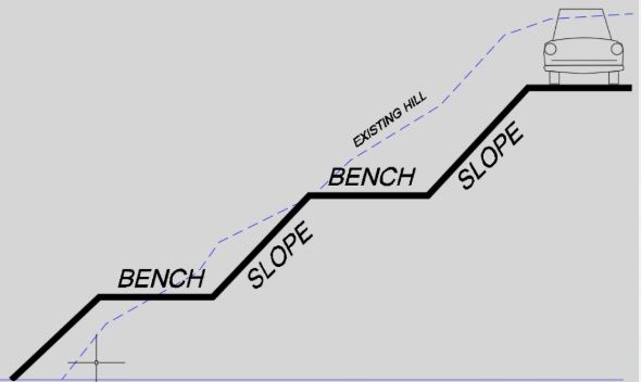
- reducing height or regrading
- adding a stabilising berm at the toe
Often the most reliable (and sometimes the cheapest) solution where space allows.
b) Drainage control
- surface drains and lined catch drains
- subsurface drains (ag drains, strip drains)
- horizontal drains in cut slopes
- toe drains and relief wells
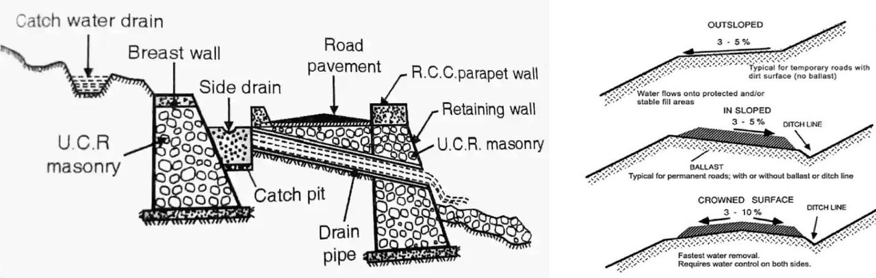
Drainage is frequently the highest "value for money" improvement because it targets pore pressure the common trigger.
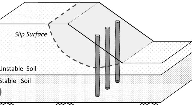
c) Structural solutions
- retaining walls (gravity, cantilever, anchored)
- soil nails, rock bolts, anchors
- shotcrete facing for rock/soil support
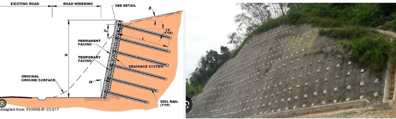
- piled solutions where deep-seated movement is a concern
d) Erosion protection and vegetation
- hydroseeding, turf reinforcement mats
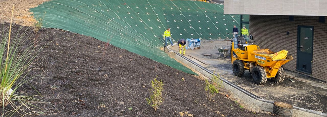
- rock armour, geofabrics, erosion blankets
- managing concentrated flows and outlet scour
Vegetation can help with surface stability and erosion, but it's not a substitute for proper geotechnical design where global stability is critical.
9) Monitoring and maintenance
For slopes with higher consequences or uncertainty, monitoring can be essential:
- survey prisms, inclinometers, piezometers
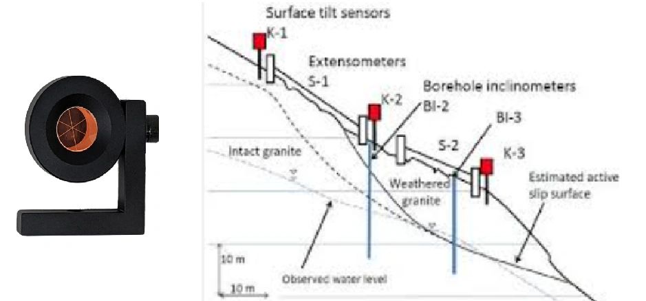
- crack monitoring and visual inspections
- rainfall thresholds and trigger action response plans (TARPs)
Long-term performance is often governed by maintenance of drainage, outlets, and crest controls.
10) Practical takeaways for projects
- Most slope issues are water + geometry + weak layers in some combination.
- Invest early in a good ground model and realistic groundwater assumptions.
- Choose stabilisation that addresses the actual mechanism not just symptoms.
- Prioritise drainage and constructability; many "strong" designs fail due to poor water management or difficult installation.
Need a slope stability assessment?
If you're planning an excavation, subdivision earthworks, road cutting, or embankment early geotechnical input can prevent expensive redesigns and construction delays. At Geotechnical Designs, we provide site-specific slope stability assessments and practical stabilisation options suited to slope conditions and construction methods.