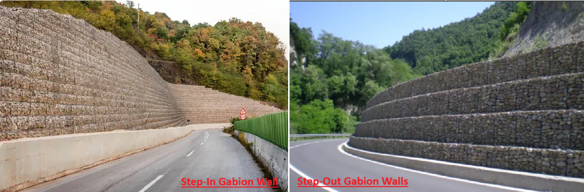
1.What are Step-In and Step-Out Gabion Walls?
- Step outside (front stepping / exposed face batter): wall “leans back” toward the soil, with steps visible on the front.
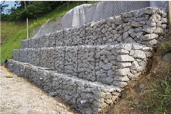 Figure 1 - Step Out Gabion Wall
- Step inside (back stepping / soil-side batter): steps are on the retained soil side; the front face looks more vertical.
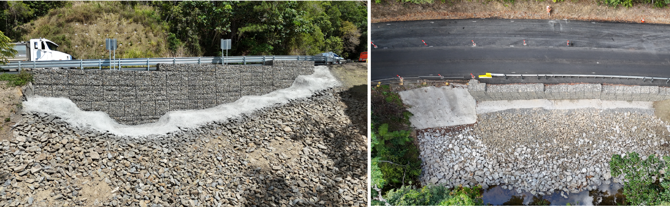 Figure 2 - Reconstruction works at locations on the Kennedy Highway (Kuranda Range Road) damaged during Tropical Cyclone Jasper
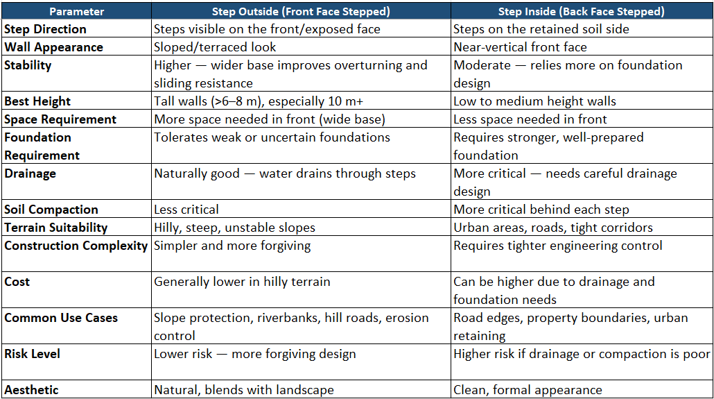
Table 1- Difference Between Between Step Out and Step in Gabion Walls
2.Steps in Designing a Gabion Wall
1.Determine the type of retaining structure
As provided in AS4678-2002 Appencdix A and the required height and overall configuration of the gabion wall**. Here we will adopt retaining structure Type B for moderate damage and loss of services. Even in GAWAC3.0 software we will adopt retaining structure B as shown in below Figure 3.
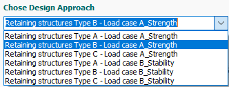 Figure 3 - Design Approach adopted in GAWAC3.0
A common starting point is to expand the wall's profile by adding standard 1m x 1m wire mesh units at the base.
2. Determine load combination for strength limit state
Using AS4678-2002 Appendix J where the load factor for dead load (G) of structure, soil on and behind the structure as been considered as 1.25. Where are load factor for live load of traffic (Q) is considered as 1.5.
Total load = 1.25 G+1.5 Q
As we are adopting load case A for strength in software as shown in Figure 3, so it will take care of load factor for dead weight. However, we have to apply the load factor for the live load, that will be 1.5*10=15kM/m2.
3. Apply reduction factor to geotechnical parameters
From AS4678-2002 table 5.1A will provide material strength and serviceability uncertainty factors for soils. Here we will consider that our soil is in-situ material. Therefor the adopted uncertainty factors are: Friction angle - 0.85 Cohesion - 0.70
For soil at the back of the wall - Friction angle - tan-1(0.85*(tan30)) = 26.13degrees
For foundation F1 Friction angle - tan-1(0.85*(tan29)) = 25.22 degrees Cohesion - 0.7*15 = 10.5 KN/m2
For Foundation F2 Friction angle - tan-1(0.85*(tan30)) = 26.13 degrees Cohesion - 0.7*20 = 14.0 KN/m2
3. Stability Check
Perform a rigorous stability check to ensure the structure can resist overturning and sliding as shown in Figure4. This analysis must be conducted at the interface of every individual stacked unit as well as at the primary foundation face.
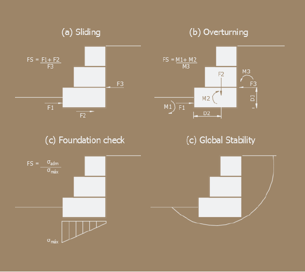 Figure 4 - Type of analysis – Gabion wall
Confirm that the resulting pressure at the foundation level remains within the "middle third" of the base to prevent tension as shown in Figure 3. Additionally, verify that the total bearing pressure stays securely below the soil’s ultimate bearing capacity. Lets have stability check and comparison of both types of gabion walls.
Step Out Gabion Wall
The soil properties and loading shown in the Figure 5 are actual properties without reduction factors and load factors respectively. However, in the analysis reduced values of soil properties have been used.
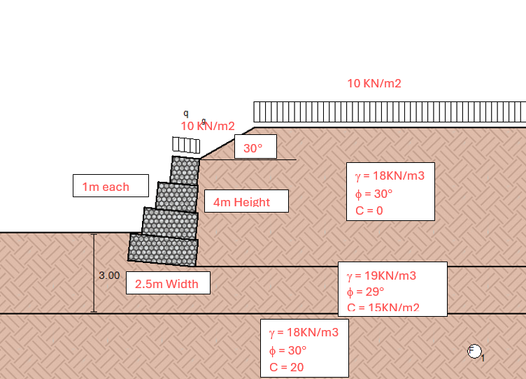
Figure 5 - Step Out Gabion Wall Details
Here I have used Maccaferri GAWAC3.0 software to do the analysis of this wall. Now lets see the analysis.
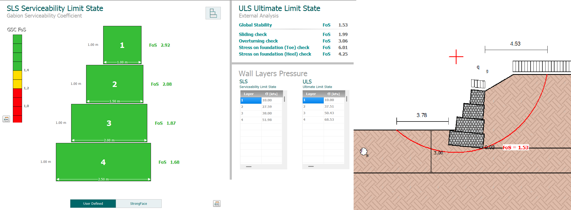 Figure 6- Step Out Gabion Wall Stability Analysis
Step In Gabion Wall
The soil properties and loading shown in the Figure 7 are actual properties without reduction factors and load factors respectively. However, in the analysis reduced values of soil properties have been used.
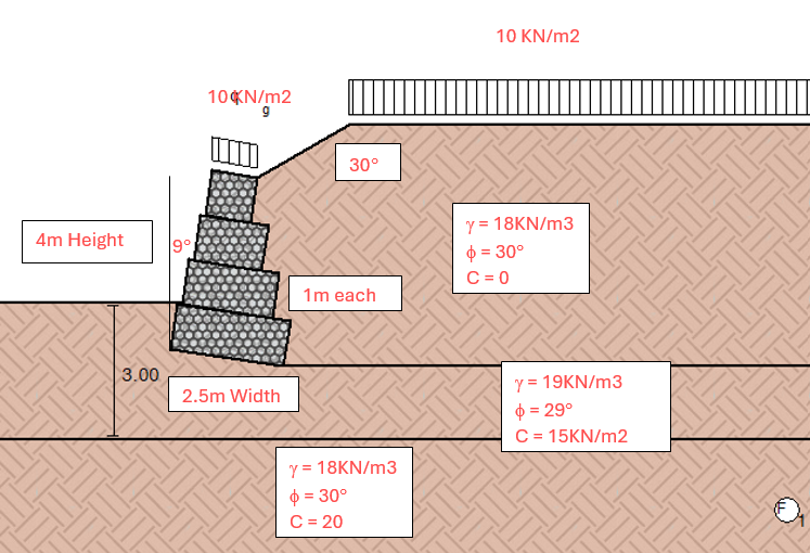
Figure 7 - Step In Gabion Wall Details Here I have used Maccaferri GAWAC3.0 software to do the analysis of this wall. Now lets see the analysis.
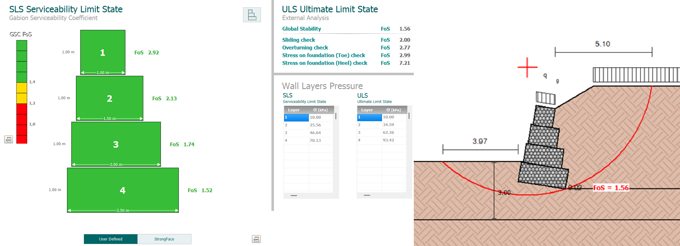
Figure 8 - Step IN Gabion Wall Stability Results
4. Conclusion
Both step-out and step-in gabion wall configurations can be designed to satisfy the key external stability requirements including sliding resistance, overturning resistance, and acceptable bearing pressure distribution at the foundation, when the design process follows AS4678 load combinations, applies appropriate parameter reduction/uncertainty factors, and checks stability at the foundation interface and at each stacked unit interface (as outlined in the article’s methodology using GAWAC3.0). In practice, this means the selection between step-out and step-in walls becomes less about “one being stable and the other not,” and more about project constraints and constructability: step-out walls offer a clearly battered, exposed front profile that can be advantageous for robustness and visual inspection, while step-in walls can provide a more vertical-looking front face (useful where frontage, aesthetics, or boundary constraints matter) without compromising stability provided the final design continues to demonstrate compressive contact across the base and bearing pressures remain within allowable limits for the founding material.